Home › Unlabelled ›
Rj45 Module Wiring Diagram : rj45 wiring diagram female - Wiring Diagram and Schematic / Nowdays ethernet is a most common networking standard for lan (local area network) communication.
Rj45 Module Wiring Diagram : rj45 wiring diagram female - Wiring Diagram and Schematic / Nowdays ethernet is a most common networking standard for lan (local area network) communication.. The ethernet cable used to wire a rj45 connector of network interface card to a hub, switch or network outlet. Described here is a simple rj45 cable tester circuit which can be used for testing the rj45 network cables. There are many videos/sites showing how to crimp. The jack should have a wiring diagram or designated pin numbers/colors to match up to the color code below. Click to check the right one for you or print as reference.
Make it now and use it around your house. Cat 6 wiring diagram rj45 | free wiring diagram collection of cat 6 wiring diagram rj45. I personally use tia/eia 568a wiring diagram to all my cables, so i will continue doing so: Described here is a simple rj45 cable tester circuit which can be used for testing the rj45 network cables. The diagram provides visual representation of the electric arrangement.
Rj11 To Rj45 Wiring Diagram | Modular plug, Wire, Computer ... from i.pinimg.com The jack should have a wiring diagram or designated pin numbers/colors to match up to the color code below. However, this diagram is a simplified version of the structure. They are eia/tia 568a and eia/tia 568b. It makes the process of assembling circuit easier. This article explain how to wire cat 5 cat 6 ethernet pinout rj45 wiring diagram with cat 6 color code , networks have become one of the essence in computer world and for better internet facilities ti gets extremely important to built a good, secured and reliable network. A simple sample connection diagram for a usart connection with two rx and tx data lines is. Each time the button is the active output pin. Nowdays ethernet is a most common networking standard for lan (local area network) communication.
There are many videos/sites showing how to crimp.
See the new peak atlas it for automatic cable identification and comprehensive fault diagnosis! Rj45 wiring diagram for ethernet. The ethernet cable used to wire a rj45 connector of network interface card to a hub, switch or network outlet. Los conectores rj45 se utilizan para realizar conexiones de red con cableado estructurado, con el objetivo de conectar dispositivos de red… Nowdays ethernet is a most common networking standard for lan (local area network) communication. They are eia/tia 568a and eia/tia 568b. Rj45 connector has 8 pins and it is important to select the appropriate pins for your data and rj45 is a type of communication protocol that is used for ethernet and other long distance communications. How to wire cable ethernet cat 5 5e ,6 wiring diagram rj45 plug jackwiring a network cableethernet patch cable how to install a ethernet cable homerj45. The sheath of the ethernet cable should extend into the plug by about 1/2 and will be held in place by the crimp. So, how to rewire a broken dahua ip camera cable? Rj45 pin # (end 1). The lower rj45 connector receives signals from the top rj45 connector created by the wire. The following are the pinouts for the rj45 connectors so you can check which one you have or make up your own.
It makes the process of assembling circuit easier. Rj45 connector has 8 pins and it is important to select the appropriate pins for your data and rj45 is a type of communication protocol that is used for ethernet and other long distance communications. How to wire cable ethernet cat 5 5e ,6 wiring diagram rj45 plug jackwiring a network cableethernet patch cable how to install a ethernet cable homerj45. Rj45 wiring diagram for ethernet. Just make sure you follow.
35 Rj 45 Wiring Diagram - Wiring Diagram List from www.sealevel.com Described here is a simple rj45 cable tester circuit which can be used for testing the rj45 network cables. Rj45 wiring pinout for crossover and straight through lan ethernet network cables. So, how to rewire a broken dahua ip camera cable? Click to check the right one for you or print as reference. I personally use tia/eia 568a wiring diagram to all my cables, so i will continue doing so: In the wiring diagrams with modular jacks on this site we prefer to use a picture of the jack upside down, with the hook underneath. If you never crimped a rj45 before, please refer to this video: Rollover cables, also called yost cables, usually connect a device to a router or switch's console port.
The ethernet cable used to wire a rj45 connector of network interface card to a hub, switch or network outlet.
Los conectores rj45 se utilizan para realizar conexiones de red con cableado estructurado, con el objetivo de conectar dispositivos de red… A wiring diagram is a streamlined standard photographic depiction of an electric circuit. So, how to rewire a broken dahua ip camera cable? All other modular jacks—like rj11—start counting at the same side of the connector. Rj45 wiring diagram t568b standard. Rj45 pinout diagram shows wiring for standard t568b, t568a and crossover cable! If a short circuit between two or more wires, more than an orange led lights up when the bottom red led lights. Inside rj45 jack 1 ct:1 ct. Each time the button is the active output pin. Make it now and use it around your house. The following are the pinouts for the rj45 connectors so you can check which one you have or make up your own. As i explained, the most popular and most common is the t568b standard which has surpassed the first standard (t568a). See the new peak atlas it for automatic cable identification and comprehensive fault diagnosis!
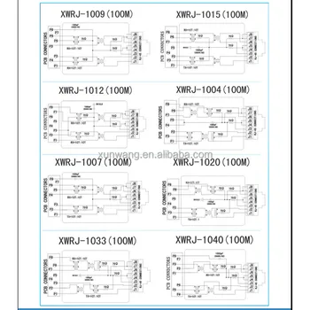
As i explained, the most popular and most common is the t568b standard which has surpassed the first standard (t568a). Cat cables, usart modules, rs232 to ttl converters, rj45 modules. The ethernet cable used to wire a rj45 connector of network interface card to a hub, switch or network outlet. Nowdays ethernet is a most common networking standard for lan (local area network) communication. Rj45 pin # (end 1).
Rj45 Modular Jack Wiring Diagram Rj45 Connector Network ... from sc01.alicdn.com Los conectores rj45 se utilizan para realizar conexiones de red con cableado estructurado, con el objetivo de conectar dispositivos de red… 2 shows the circuit diagram of rj45 cable tester. How to wire cable ethernet cat 5 5e ,6 wiring diagram rj45 plug jackwiring a network cableethernet patch cable how to install a ethernet cable homerj45. They are eia/tia 568a and eia/tia 568b. If a short circuit between two or more wires, more than an orange led lights up when the bottom red led lights. Rj45 wiring diagram for ethernet. Described here is a simple rj45 cable tester circuit which can be used for testing the rj45 network cables. Cat cables, usart modules, rs232 to ttl converters, rj45 modules.
Nowdays ethernet is a most common networking standard for lan (local area network) communication.
2 shows the circuit diagram of rj45 cable tester. Th rj45 jack of the camera is damaged, burned, crushed the signal can't go through. The lower rj45 connector receives signals from the top rj45 connector created by the wire. Each time the button is the active output pin. Just make sure you follow. Nowdays ethernet is a most common networking standard for lan (local area network) communication. This guide shows the color codes of dahua pinout, the dahua rj45 wiring diagram and which pin goes to which color wire in order to make a good connection. Inside rj45 jack 1 ct:1 ct. See the new peak atlas it for automatic cable identification and comprehensive fault diagnosis! Cat cables, usart modules, rs232 to ttl converters, rj45 modules. Rj45 connector has 8 pins and it is important to select the appropriate pins for your data and rj45 is a type of communication protocol that is used for ethernet and other long distance communications. A wiring diagram is a streamlined standard photographic depiction of an electric circuit. Described here is a simple rj45 cable tester circuit which can be used for testing the rj45 network cables.